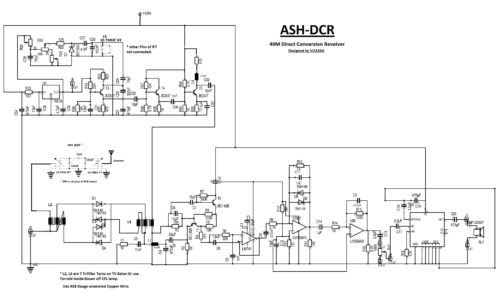
Built this Direct Conversion RX called ASH-DCR. I named it myself 🙂 as it is designed by VU2ASH OM Ashok Joshi. It is a very simple design and a good first project for SWLs entering the homebrewing bandwagon. It mostly uses readily available components and nothing is hard to find. For coils in VFO and Band Pass Filter 10.7 Mhz IFTs can be used without any modification. The Double Balanced Modulator has two Trifilar windings which can be wound either on Binocular TV Balun Core or a toroid scavenged from a broken CFL Lamp.
The Bypass filter shown in the circuit is not part of the PCB layout and I have built it on a separate PCB. The VFO and BPF capacitors are selected for the 7Mhz or 40M Amateur band, these can be easily changed for 20M band. VFO is based on varactor tuning and I have used BB109 varactor diode which is available in most of the components shops for around Rs. 10/-. A 10 turn 10K pot is used for tuning. Also the Audio amplifier uses a LM380 IC and is very loud with a speaker (I have only left a headphone jack due to space limitation in my box).
Circuit Diagram
PCB Layout for the Receiver

PDF File: Download the PCB layout PDF file for Toner Transfer
PDF File: Download the Component Layout for ASH DCR
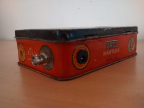
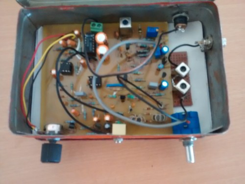
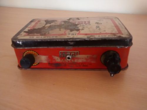
Some pictures of my homebrewed ASH DCR
Small toroids from a CFL lamp can be seen on the left of the blue pot in above picture. Also the BPF is above the blue pot.
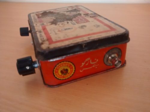
This box was lying in the junk in my shack. Such tin boxes are very useful to cut down on RFI in sensitive circuits like these.
If you have any suggestions or questions, write to me in the comments section below !
Permalink
Is it possible to make DCR by using RF DAC and RF ADC’s. example I got one Programmable DAC by Analog Device AD 9119/29. it is 11-14 bit DAC and have bandwidth upto 9.1GHz. By using a ADC of same frequency response it is possible to construct a small scale or experimental DCR.
Permalink
Why not ?? take a look at this work in progress project : https://groups.google.com/forum/#!forum/hermes-lite
Also this should give you some basic understanding: http://www.arrl.org/files/file/QEX_Next_Issue/Jan-Feb_2011/QEX_1_11_Ahlstrom.pdf
Permalink
Sir, Where can I find the 10.7MHz IFT coils?
They are hard to find in India.
Permalink
Hi Rushiraj,
Ask for FM IFT in a radio repair shop. If you don’t find one, wind a coil yourself using 1/4 inch drinking straw. Around 40-43 turns on 28 SWG wire on a straw will get you to 7 Mhz frequency. I learned this from Farhan (designer of BITX TRX).
To wind the coils :
Use a pin to make two holes across one end of the straw.
Pass one end of the wire through them and wind them with light tension. Too much tension can collapse the straw, too less will result in very loose coil.
After 43 turns, hold the wire in place with your fingers, make another set of holes and pass the wire through it to secure the coil. Apply super-glue or Feviquick to secure the turns.
Use this coil and test the VFO on a RTL SDR/broadcast receiver to see where it tunes.. increase or decrease truns to get to the desired frequency.
73’s
Amogh
VU3DES
Permalink
Can I please have any source(s) for multi-turn pots in India?
Permalink
I get them in Pune. They are expensive though. I got original Bourns for around Rs. 175. Could only find this online: http://sonlineshop.com/index.php?route=product/product&path=62_135&product_id=1275
Permalink
R10 has to be 1 MOhm, not 1 KOhm.