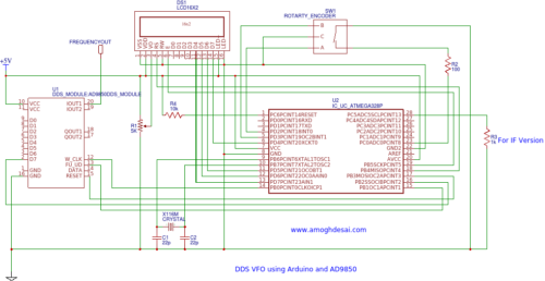
I put together this breadboard version of an AD7C designed DDS VFO demo with a little help from pen friend AB9XC Pravin Kumar Anandan. AD7C designed this basic VFO around a Arduino UNO. I wanted to further save some cost and build it using a bare Atmega328P chip, where Pravin had been a great help. I used this diagram for reference.
Here’s the circuit Diagram I created:
Download the PDF Circuit Diagram.
Download the Sketch I used for this test from here: AD9850_LCD_ROTARY_IF__WITH_1_HZ_RES.zip
Download the Rotary Encoder Library for Arduino from here: Rotary.zip
Extract the the content of Rotary.zip to the “libraries” folder inside your Arduino IDE Installation folder. (Mine is at C:\Program Files\Arduino\libraries). Burn the sketch to a bare Atmega328P IC and build the circuit.
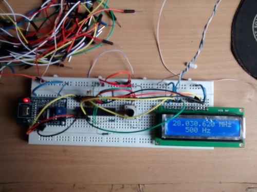
My breadboard VFO setup looked like this:

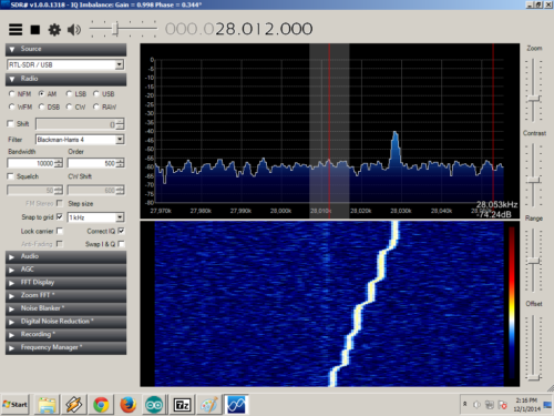
Tested it using a RTL SDR dongle.

My dongle seems to be a couple of KHz off the frequency :), and the DDS works just as it is intended!
Do let me know how you find this circuit, or if you have any questions or suggestions to improve this design, leave your comments below.

Permalink
For my homebrew receivers, trx, i used to make the vfo and stabilized it with the tailore made/wizely choosed components. But, now a days the world has become digital with precise commercial equipments. Mechanical vfo dont stand a chance, even the 50hz shift is pointed out by others. In this the ultimate saviour for homebrewer is DDS VFO. It’s very nice to see something different than other regular DDS VFO. congrats.
Permalink
GR8 project.
I see that you are powering your module / project with 5V, just wanted to know if the DDS Clock Ref. gets hot ?
regards.
Permalink
I mounted your dds vfo works up to 44Mhz at the D7 output as verified on the frequency meter. But the 16×2 LCD shows nothing. Can you help solve the problem? I am Brazilian and my English is from Google.
PY3UB – Amateur Radio.